
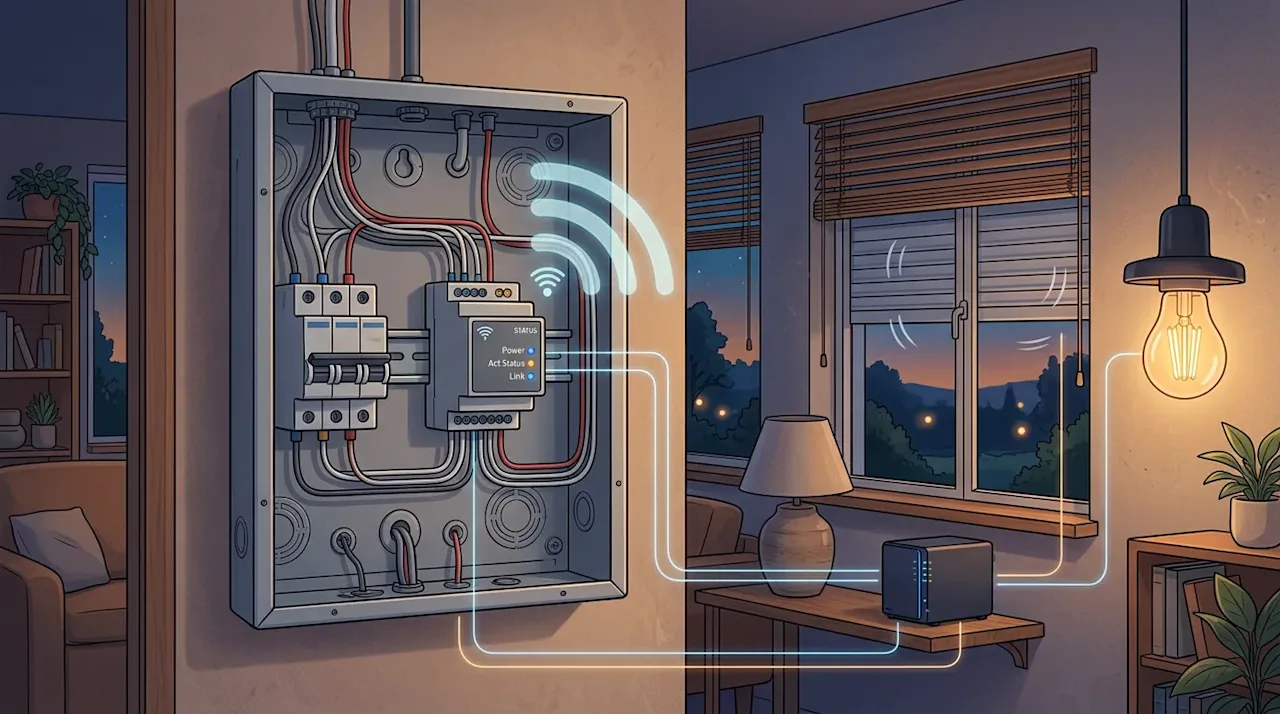
The shutters and a handful of the lights in our flat are run by a grey DIN-rail box in the electrical panel: a Gerber Prime 6000-series controller. Out of the box you control it with a phone app called Home Mate 2, through the vendor's cloud. The rest of our smart home runs through Home Assistant, so this box was the holdout (and shutters are exactly the kind of thing you want in automations).
There is no Home Assistant integration for it and no published API. But the controller has its own little web interface, and that web interface has to talk to the hardware somehow. Once I'd worked out how it does that, getting it into Home Assistant was mostly plumbing. This post is the whole route, step by step, for anyone else with one of these units in their panel. The notes and code live in two public repos: gerber-prime-6000-local-api (the API and a Python client) and gerber-prime-6000-mqtt-bridge (the Home Assistant side).
GitHub Repository danielrosehill/gerber-prime-6000-local-api Unofficial local HTTP API (no cloud) for Gerber Prime 6000 / PSC05 smart-home controllers — reverse-engineered notes + Python/curl/Home Assistant samples MITUpdated Nov 2026 gerber-primegpb-6000gps-6000home-assistanthome-mate-2 View on GitHub GitHub Repository danielrosehill/gerber-prime-6000-mqtt-bridge Local MQTT bridge (HA discovery) for Gerber Prime 6000-series relay/shutter controllers — no vendor cloud PythonMITUpdated Nov 2026 View on GitHubA disclaimer before anything else: none of this is official or endorsed by Gerber. The commands below switch real relays and move real shutters, so test on something harmless first.
Is this your controller?
The family goes by a few model names: GPS-6000 ("Shutter module 5A×4, Relay up to 5A×8"), GPB-6000 and so on. It has eight outputs, populated with hot-plug dongles (relay, dimmer or curtain/shutter), and eight inputs. The part that matters here is the Wi-Fi control module, which identifies itself as PSC05 (there's a sibling PSC03).
The quickest test is a Wi-Fi scan near the panel. If you see a network called PSC05-xx:xx:xx:xx:xx:xx (the suffix is the module's Wi-Fi MAC, which is also printed on the label), this guide applies to you.
Step 1: Join the controller's setup Wi-Fi
Out of the box the module runs its own access point for configuration. The defaults are published in the FCC manual, so I'm not giving anything away here:
Setup Wi-Fi password:
12345678Controller address on that network:
10.10.10.254Web UI and API login:
admin/888888(HTTP Basic auth)
(The six-digit 888888 can't be the Wi-Fi key, because WPA needs at least eight characters. That's how I ended up trying 12345678, which worked first time.)
You can join from a phone or laptop and open http://10.10.10.254/ in a browser. I didn't want my laptop leaving the main network while I was working, so I did it from the home server with a cheap USB Wi-Fi adapter. The important part is pinning the connection so it can't take over the default route:
IF=wlx...   # your USB adapter's interface name
nmcli dev wifi list ifname "$IF" --rescan yes | grep -i PSC05

sudo nmcli connection add type wifi ifname "$IF" con-name gerber-ap \
     ssid "PSC05-xx:xx:xx:xx:xx:xx"
sudo nmcli connection modify gerber-ap \
     wifi-sec.key-mgmt wpa-psk wifi-sec.psk 12345678 \
     ipv4.never-default yes ipv6.never-default yes ipv4.route-metric 900
sudo nmcli connection up gerber-ap

curl -u admin:888888 http://10.10.10.254/
The server picks up a 10.10.10.x address and the web UI answers. It's a plain 2018-era admin page (Devices, Rooms, Scenes, Macros, Settings) served by an old Apache.
Step 2: How the web page talks to the controller
The page's own JavaScript (js/global.js, which you can open in the browser like any other file) shows how it does its job. Everything goes through two CGI endpoints, both behind the same Basic auth:
/sdk.cgi: device control and status (read every channel, switch relays, move shutters)/network.cgi: Wi-Fi and network settings
/sdk.cgi takes a POST with a single form field called json. The value is a small command object:
{"control":{"cmd":"switch","uid":257,"chid":3,"val":255}}There's one quirk that will cost you an evening if nobody tells you: the page double-encodes that JSON, as encodeURIComponent(encodeURI(json)), before sending it. The response is URI-encoded JSON too, so you decode it before parsing. A response with respcode: 100 means success. In Python, the whole client comes down to this:
import base64, json, urllib.parse, urllib.request

HOST, USER, PASS = "10.10.10.254", "admin", "888888"
AUTH = "Basic " + base64.b64encode(f"{USER}:{PASS}".encode()).decode()

def encode_uri(s):           return urllib.parse.quote(s, safe="!#$&'()*+,-./:;=?@_~")
def encode_uri_component(s): return urllib.parse.quote(s, safe="!'()*-._~")

def sdk(cmd, **fields):
    payload = json.dumps({"control": {"cmd": cmd, **fields}}, separators=(",", ":"))
    body = "json=" + encode_uri_component(encode_uri(payload))
    req = urllib.request.Request(
        f"http://{HOST}/sdk.cgi", data=body.encode(),
        headers={"Authorization": AUTH,
                 "Content-Type": "application/x-www-form-urlencoded"})
    raw = urllib.request.urlopen(req, timeout=10).read().decode(errors="replace")
    resp = json.loads(urllib.parse.unquote(raw))
    if resp["control"]["respcode"] != 100:
        raise RuntimeError(resp["control"])
    return resp
Step 3: Read your channel layout
The first call to make is the read-only get_all_device, which returns the full inventory:
resp = sdk("get_all_device")
dev = resp["device"][0]
print("uid:", dev["uid"])
for ch in dev["channel"]:
    print(ch["chid"], ch["name"], "type", ch["ctrltype"], "value", ch["basicvalue"])
Mine came back as one device, uid 257, with six on/off relays (channels 1 to 6) and one roller shutter (channel 7). The ctrltype tells you which is which:
23: an on/off relay.basicvalueis0for off and255for on.26: a roller shutter.basicvalueis a position from0to99.
There's also a pan27_info block with the shutter travel times (mine is set to about 20 seconds) and the Modbus settings, which I'll come back to.
Switching is then one call. To turn relay 3 on and off:
sdk("switch", uid=257, chid=3, val=255)   # on
sdk("switch", uid=257, chid=3, val=0)     # off
If you'd rather stay in the shell, the repo has raw curl versions with a little encoding helper, and examples/gerber_client.py wraps all of this as a command-line tool.
Step 4: Get the controller onto your own network
Talking to it over its setup Wi-Fi is fine for experimenting, but Home Assistant needs to reach it on the LAN. The module can switch from access-point mode to joining your Wi-Fi as a client ("STA" mode), and this was the step that took longest.
/network.cgi has all the right commands (setstassid, setstapwd, setwifimode=STA, wificommit), and they're the same ones the web page sends. Driving them directly never produced a working join for me, across WPA2, WPA2/WPA3 and even an open network. My best guess is that the raw calls don't set the network's security type, and the web page does. The good news is that a failed join is harmless: the unit reboots, can't connect, and falls back to its setup network.
What worked:
Have a network the controller can actually join. Its Wi-Fi stack is old, so give it 2.4 GHz, WPA2-PSK, with PMF (802.11w) off and no fast roaming. In my case only a dedicated legacy 2.4 GHz network on the IoT side did it.
In the web UI, go to Settings → Wi-Fi → STA Mode and pick the network from the scanned list rather than typing it.
Commit. Mine went quiet at this point (no setup network, not on the LAN), which looked alarming.
Power-cycle the unit (breaker off, breaker on). It came back joined to the network with a DHCP lease.
Give it a static DHCP reservation on your router, so Home Assistant always finds it at the same address. After a reboot to check, mine was back on its reserved address in about 16 seconds.
A warning about recovery, because it's the one mistake that would really hurt. If the Wi-Fi config gets wedged, power-cycle it. That's non-destructive: all the channels, names and scenes survive. Don't hold the Reset button for five seconds, because that's a factory reset and wipes the lot.
If you can't get STA mode to take at all, there's a stopgap I used for a day: leave a machine joined to the setup Wi-Fi (as in step 1) and forward a port from the LAN to the controller with socat. Home Assistant can then use that machine's address:
socat TCP-LISTEN:8456,fork,reuseaddr TCP:10.10.10.254:80Step 5: Into Home Assistant with an MQTT bridge
My first sketch was all Home Assistant YAML: a rest_command for switching, a command_line sensor polling get_all_device, and template switches on top. It works, but it's a lot of YAML, the double encoding means precomputing a payload for every channel and state, and recent Home Assistant releases dropped the legacy template syntax it relied on.
So I wrote a small Python service instead. It polls the controller, publishes state to MQTT, and announces everything through Home Assistant's MQTT discovery. Home Assistant then creates a single device with a switch for every relay and a positional cover for every shutter, and you write no YAML at all:
Home Assistant ──MQTT──▶ broker ◀──MQTT── bridge ──HTTP──▶ controller (/sdk.cgi)The setup assumes you already have an MQTT broker that Home Assistant's MQTT integration is connected to (the Mosquitto add-on is fine). Then:
git clone https://github.com/danielrosehill/gerber-prime-6000-mqtt-bridge
cd gerber-prime-6000-mqtt-bridge
cp .env.example .env
cp docker-compose.example.yml docker-compose.yml
# edit .env, then:
docker compose up -d --build
The .env is where your channel layout from step 3 goes:
GERBER_HOST=192.168.1.80        # the controller's reserved LAN address
GERBER_USER=admin
GERBER_PASS=888888
GERBER_UID=257                  # from get_all_device
RELAY_CHIDS=1,2,3,4,5,6         # ctrltype 23
SHUTTER_CHIDS=7                 # ctrltype 26

MQTT_HOST=192.168.1.10          # your broker
MQTT_PORT=1883
MQTT_USER=
MQTT_PASS=

MQTT_BASE_TOPIC=gerber/gps6000
DEVICE_NAME=Gerber Prime 6000
POLL_INTERVAL=10
(No Docker? pip install "paho-mqtt>=2.0" and run gerber_mqtt_bridge.py with the same variables set in the environment.)
Within a few seconds, a "Gerber Prime 6000" device turns up under Settings → Devices & Services → MQTT. Rename the generic "Relay N" entities to whatever each one actually switches, and from then on they behave like any other Home Assistant entity, in dashboards, automations and voice.
Discovery itself is just a retained config message per entity. A relay, for example:
cfg = {
    "name": f"Relay {chid}",
    "unique_id": f"{NODE_ID}_relay_{chid}",
    "state_topic": f"{BASE}/relay/{chid}/state",
    "command_topic": f"{BASE}/relay/{chid}/set",
    "availability_topic": f"{BASE}/availability",
    "device": DEVICE,
}
client.publish(f"homeassistant/switch/{NODE_ID}/relay_{chid}/config",
               json.dumps(cfg), retain=True)
The bridge polls every ten seconds, publishes only what changed, and polls again a second after any command so the dashboard catches up quickly. If three polls in a row fail, it marks the device unavailable.
Three things that will catch you out
The shutter scale is backwards. The controller counts 0 as fully open and 99 as fully closed. Home Assistant counts the other way: 100 is open and 0 is closed. If you pass the value straight through, everything breaks at once (the position reads inverted, "open" closes the shutter, and 100% sends it shut). The bridge converts in both directions in one place:
SHUTTER_MAX = 99

def device_to_ha(val):   # device 0 (open)..99 (closed) -> HA 100..0
    return round((SHUTTER_MAX - val) * 100 / SHUTTER_MAX)

def ha_to_device(pos):   # HA 100 (open)..0 (closed) -> device 0..99
    return round((100 - pos) * SHUTTER_MAX / 100)
There's no stop command. I went through the web page's own JavaScript looking for one. The controller's own UI only has a 0 to 99 position slider, and the controller handles the timed travel itself. So the Home Assistant cover has open, close and set-position, but no stop button. The position also updates only once travel finishes, so the dashboard lags the real shutter by the travel time.
Availability has to be re-asserted after every MQTT reconnect. The bridge sets an MQTT "last will" of offline and publishes availability only when it changes. After a broker restart, that retained offline stays on the topic, but the bridge still thinks it last said online, so it never corrects it. Every entity then sits "unavailable" in Home Assistant while the bridge polls away happily. The fix is to forget the last state on connect:
def on_connect(self, client, userdata, flags, reason_code, properties):
    client.subscribe(f"{BASE}/relay/+/set")
    client.subscribe(f"{BASE}/shutter/+/set")
    client.subscribe(f"{BASE}/shutter/+/set_position")
    publish_discovery(client)
    self.last = {}        # republish every state
    self.online = None    # force the next good poll to publish "online"
    self.poll_now.set()
If your entities ever look dead, check the retained topic before you blame the controller:
mosquitto_sub -h <broker> -u <user> -P <pass> -t 'gerber/gps6000/#' -v -W 5availability offline next to current relay states means it's this bug, not an outage.
What about Modbus?
The RJ11 port on the controller is RS485/Modbus, and that was my original plan: an RS485-to-Wi-Fi bridge polling the box as a Modbus slave. The settings are in the web UI under Settings → PAN27 Information → Modbus Mode (it defaults to master; switch it to slave if you want to poll it from outside). Once the HTTP route worked I never needed it, but it's there as a fallback if your unit won't get onto Wi-Fi, or if you'd rather have a wired link.
Where it stands
The controller is now in Home Assistant with no vendor cloud in the loop and no extra hardware beyond a server that was already running. The relays and the shutter are ordinary entities like everything else (which, for a box that shipped expecting a phone app, is the whole point). A few things are still open: dimmer channels (I have none to test against), a pure-API way into STA mode, and whatever other variants of this hardware are out there. If you have one of these units and work any of that out, pull requests on the API repo are very welcome.
If you're building out a Home Assistant setup, I've also written about a custom wake word for Home Assistant and an NFC grocery list built on it.
